Our LOBBYIST required a number of circuits in order to achieve full functionality. To show you how we did it, we've detailed our circuits below for each piece of functionality.
Pinout Diagram
Power Distribution

| power_distribution.pdf |
Two in-series 7.2V NiCd batteries provides the power to the LOBBYIST. A 10A fuse is used to guard against overdrawing current, and a SPST switch is used as the master kill switch. A 14.4V power rail is connected directly after the switch to provide power to the Lift fan, Propulsion lans, and LED strips on the DMC. A LM2596 buck converter is used to step down the 14.4V to create an 8V power line. This is used to power the motor of the linear potentiometer of the DMC. A different LM2596 buck converter is used to step down the 14.4V to create a 6V power line. This is used to power to the TIVA, which provides the 5V and 3.3V power lines.
Lift

| lift_fan_motor_drive.pdf |
The lift motor drive uses an N channel BJT (2N3904) that is turned on and off by the TIVA, which in turn controls a P-channel MOSFET (IRF5305) that drives the Lift Fan. The multi-step drive ensures that the current and voltage capabilities of the TIVA will not be exceeded. We chose to use a P-channel MOSFET rather than an N-channel so that we could ensure that the lift fan was grounded on one side. The two diodes separating the MOSFET from the fan are used to drop down voltage according to the fan motor's input specifications.
Propulsion

| propulsion.pdf |
2 EPS-100C-BS brushed motors is used to drive the propulsion propellers. A TLE-5206 motor driver is used to drive each motor using drive-brake mode. This configuration allows the motor to be driven through PWM in either direction to achieve any voltage up to 14.4 V.
The Display of Memory and Commitment (DMC)

| dmc.pdf |
A PIC12F752 microcontroller is used to control the DMC. The PIC, in turn, is controlled by the main LOBBYIST TIVA via UART communication.
The DMC contains a motorized linear potentiometer. Since the motor requires a maximum of 800 mA, an L293 h-bridge is used as a driver. Additionally, the potentiometer output is connected to an analog input of the PIC. Thus, using software control, the PIC can control the height of the potentiometer slide.
Finally, the DMC is required to display the team color of the LOBBYIST. Each color has its own PIC pin that is connected to the gate of a 2N7000 NPN MOSFET. The drain of the each of these MOSFET is connected to an LED strip. Thus, by outputting a logical high on the PIC, the LED strip activates. To signify red, one MOSFET is attached to the red LED branch of the LED strip. To signify blue, the other MOSFET is attached to both the blue and green branches of the LED strip. The resulting blue shade is very similar to the blue of the genie from Aladdin.
Ball Hitting Swords
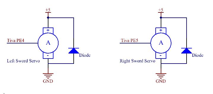
| the_sword_servos.pdf |
Each sword was mounted on a servo. The position of the servos was controlled by the duty cycle of the PWM signal coming from the TIVA.
Badge Detection
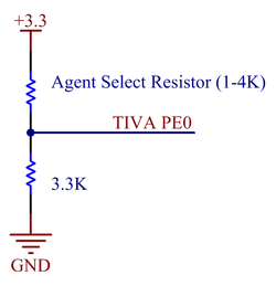
| agent_select.pdf |
Batch detection was done on basis of a simple voltage divider. Each badge contained an agent select resistor that was one of 1K, 2K, 3K, or 4K resistors depending on the badge and was given to us during the game. Using a 3.3 K load resistor on the Lobbyist and an analog voltage input to the TIVA, the correct agent number was determined.
Wireless Communication

| lobbyist_xbee.pdf |
A Digi XBee was used for radio communication. The Tiva interfaces with the XBee using API UART communication.
